
Slope Failure Causes and Prevention: Field Guide
Quick Summary
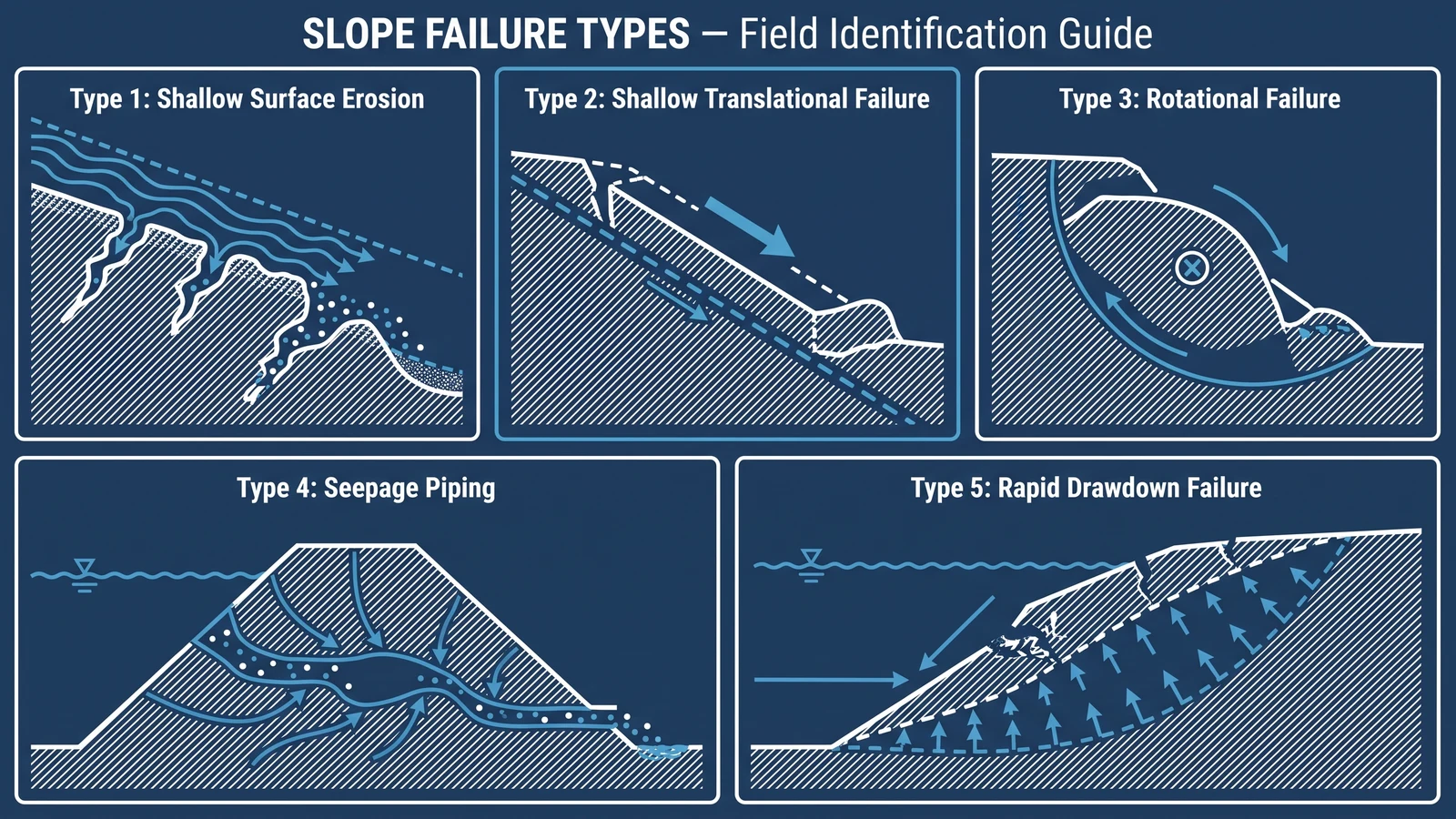
Slope failures on canal embankments, reservoir faces, and road cuttings follow recognisable patterns. This field guide covers the five main slope failure types — shallow surface erosion, shallow translational, rotational, piping, and rapid drawdown — with prevention measures for each.
Quick Answer: Slope failures on hydraulic structures fall into five types: (1) shallow surface erosion — the most common and preventable; (2) shallow translational failure — soil sliding on a weak layer; (3) rotational (deep-seated) failure — circular slip through the embankment; (4) seepage-induced piping; and (5) rapid drawdown failure — the most dangerous for reservoir slopes. Surface armour (grouted mattress, riprap) prevents Type 1 only. Types 2–5 require geotechnical analysis and engineered drainage solutions — surface armour alone is insufficient and can mask early warning signs. This guide helps engineers distinguish which type is occurring and what to do.
Slope failure on a reservoir upstream face, irrigation canal embankment, or road cutting is often described generically as "slope failure" — but the correct diagnosis is critical, because the prevention and remediation of each type differs fundamentally. Applying surface armour to a slope that is failing by rotational slip does not prevent the failure; it merely adds weight to the sliding mass. This field guide is for engineers and inspectors who need to identify slope failure type in the field and determine the appropriate response.
For prevention of surface erosion specifically, see Slope Protection for Canals and Reservoirs and Highway Slope Protection. For canal lining failure specifically, see Canal Lining Failure: 7 Common Causes.
Type 1: Shallow Surface Erosion
Field identification: Progressive removal of the slope surface — visible as a roughening or pitting of the surface, rill development, or loss of vegetative cover. The slope retains its overall geometry; only the surface layer is being removed. No tension cracks visible at the crest.
Causes: Rainfall impact, surface runoff velocity exceeding the critical shear stress of the slope material, or wave action on reservoir slopes. Unprotected clay erodes at velocities above 0.5–1.0 m/s; sand at velocities above 0.3–0.6 m/s.
Prevention and remediation: Surface armour — grouted mattress, riprap, or vegetation — matched to the design runoff velocity. See Slope Protection Guide for thickness selection. Surface erosion is the failure type that surface armour directly prevents; it does not indicate deeper instability.
Type 2: Shallow Translational Failure
Field identification: A soil mass 0.5–2.0 m thick slides downslope as a relatively intact slab, typically along a planar weak surface (an old failure plane, a clay layer, or the base of a compacted fill layer over a soft foundation). Visible as a stepped slope face — the sliding slab drops below the surrounding slope surface and a scarp appears at the upslope edge. Often triggered by rainfall saturation of the near-surface zone.
Causes: Saturated near-surface zone reducing effective stress to near-zero; pre-existing weak plane (clay seam, geological discontinuity); or high pore pressure from rain or rapid changes in pond level.
Prevention: Sub-surface drainage — lateral drains or counterfort drains installed at 3–5 m depth to intercept and drain the near-surface zone. Slope angle reduction may also be required. Surface armour does not address the cause; do not apply surface armour without first investigating the sub-surface drainage regime.
Type 3: Rotational (Deep-Seated) Failure
Field identification: A large mass of soil rotates about a circular arc through the embankment, typically involving the full height of the slope. Visible as a curved failure scarp at the crest (tension crack), a bulge at the toe, and lateral displacement of the slope face. The failed mass often retains a relatively smooth, curved upper surface. Develops over days to weeks in most cases — not instantaneous.
Causes: Factor of safety against circular slip below 1.0 — caused by overly steep slope angle for the material strength, foundation failure, or increased pore pressure. Bishop simplified method or Spencer's method (as implemented in slope stability software like Rocscience Slide or GEO5) is used for design analysis.
Prevention: Geotechnical stability analysis at design stage — confirm factor of safety ≥ 1.3 (operational) / ≥ 1.1 (seismic + flood) for all design scenarios. Surface armour adds only 1–5% to the driving moment on a deep-seated slip — it does not meaningfully increase stability. Remediation options: slope flattening, toe berms, deep drainage, ground improvement.
Type 4: Internal Erosion and Piping
Field identification: Turbid (cloudy) seepage emerging on the downstream slope or toe — the turbidity indicates active particle transport (piping). May progress from barely visible to visible spring, to boil, to void formation, to sudden internal collapse. The upstream slope surface may remain intact until the failure progresses to near-surface. This is the most dangerous failure type because it can progress to breach rapidly and with little warning.
Causes: Inadequate filter design allowing fine particles to migrate from the embankment fill into coarser zones; concentrated seepage pathways through the dam body (cracks, construction lifts, conduits); or internally unstable soils where fine particles migrate through coarse matrix under seepage gradient.
Prevention: Filter design to USACE EM 1110-2-1901 — ensure all material boundaries within the embankment satisfy filter retention and permeability criteria. Emergency response to turbid seepage: do not attempt to seal the downstream seepage exit — this increases internal pressure and accelerates piping. Lower the reservoir and call a geotechnical engineer immediately.
Type 5: Rapid Drawdown Failure
Field identification: Slope failure on the upstream (water-side) face of a reservoir or canal slope, occurring during or shortly after a rapid drop in water level. Typical failure pattern: translational slip of the upstream slope face, with a planar failure surface approximately parallel to the slope. Can be sudden (hours) once triggered. Most common on steep upstream slopes (1:2 to 1:2.5) with low-permeability fill materials.
Causes: The pore pressure in the embankment fill at the time of drawdown reflects the pre-drawdown reservoir level. When the reservoir drops rapidly, the pore pressure (and effective stress) within the slope remains elevated while the external stabilising water pressure is removed. The factor of safety against slope failure drops transiently — sometimes below 1.0.
Prevention: (a) Control drawdown rate — limit to no more than 0.3–0.5 m/day for low-permeability fills without detailed analysis; (b) increase embankment permeability by using granular fill in the outer shell; (c) install drainage blankets behind the lining to accelerate pore pressure dissipation; (d) specify filter point grouted mattress on the upstream face — it allows partial drainage through the lining, slowing pore pressure build-up during drawdown. Drawdown stability analysis (using undrained strength parameters for rapid drawdown) is required per USACE EM 1110-2-1902.
Field Identification Summary
| Failure Type | Key Field Signs | Surface Armour Effective? | Primary Prevention |
|---|---|---|---|
| Surface erosion | Rilling, roughening, loss of vegetation | Yes — directly | Grouted mattress or riprap |
| Shallow translational | Slab slide, scarp at crest, stepped face | No | Sub-surface lateral drainage |
| Deep rotational | Curved crest scarp, toe bulge, lateral movement | No — adds to driving mass | Geotechnical analysis → slope flattening / toe berm |
| Piping / internal erosion | Turbid seepage, boils, sudden void collapse | No — do not seal downstream | Filter design to EM 1110-2-1901; lower reservoir immediately |
| Rapid drawdown | Upstream face slide during/after level drop | Partial (filter point GGFM reduces pore pressure) | Control drawdown rate; drainage blanket; stability analysis |
Frequently Asked Questions
How do I tell the difference between a surface erosion problem and a shallow translational failure?
The key indicator is slope geometry. Surface erosion reduces the slope surface progressively — the overall slope angle and crest position remain unchanged. Shallow translational failure produces a visible scarp (near-vertical back wall) at the upslope edge of the failure, where the sliding mass has separated from the stable slope. The sliding mass is typically intact or in large blocks — not in small eroded particles. If you see a continuous back scarp at the crest, you have a translational failure, not surface erosion.
Can I install grouted mattress to stabilise a slope that has already failed?
Only for surface erosion (Type 1). For all other failure types, the slope must be re-engineered (drainage installed, slope angle reduced, or toe berm constructed) before any surface lining is applied. Applying grouted mattress to an actively sliding slope will not prevent the failure and may accelerate it by adding weight to the sliding mass. Always commission a geotechnical investigation for any failure that shows signs of Types 2–5 before specifying a remediation approach.
What monitoring should be in place on a reservoir embankment to detect early failure signs?
The minimum monitoring programme recommended by ICOLD Bulletin 158 (Dam Safety Management) includes: piezometers in the embankment (to monitor pore pressure); settlement monuments on the crest (to detect settlement and lateral movement); turbidity monitoring of downstream seepage (to detect piping); and regular visual inspection of upstream and downstream slopes. Trigger levels for each instrument should be set in the dam's Emergency Action Plan — readings exceeding triggers should prompt immediate engineering review.
HydroBase engineering team can review your slope condition and advise on whether surface armour (grouted mattress) is the appropriate response, or whether a geotechnical investigation is required first. Submit your slope geometry and observed signs — we will give you an honest assessment within 48 hours.
HydroBase Technical Team
HydroBase manufactures grouted mattresses (GRI GT16 compliant) in China and delivers to 30+ countries. Our engineering team provides specification support, grout mix design, and installation guidance.
About HydroBaseMore Articles
View all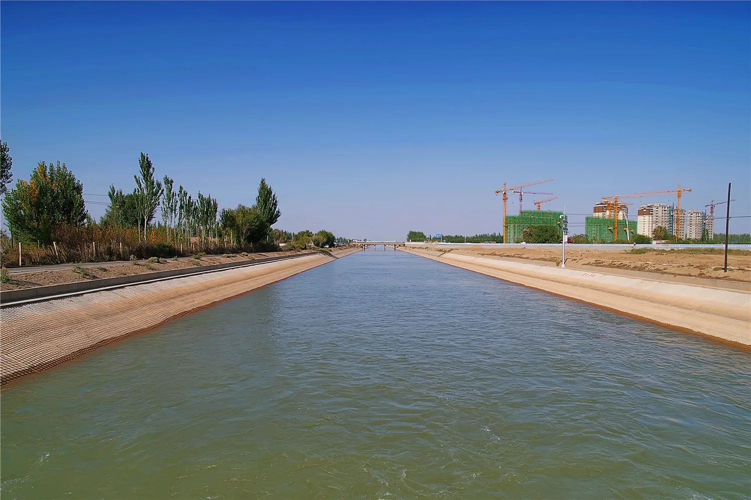
Grouted Mattress Case Studies: 5 Projects, Real Data
Five real grouted mattress installations across canal lining, river bank protection, coastal revetment, reservoir lining, and bridge pier scour — with actual project areas, design parameters, installation programmes, and post-installation performance data.
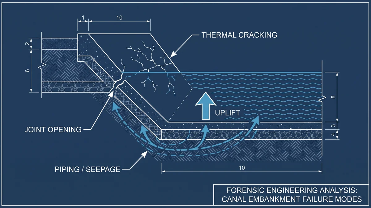
Canal Lining Failure: 7 Causes and How to Prevent Them
Canal lining failures cost irrigation authorities billions annually in emergency repairs and lost water. This forensic guide identifies the 7 most common failure causes — from joint failure to uplift — and explains how to prevent each through better specification and installation.
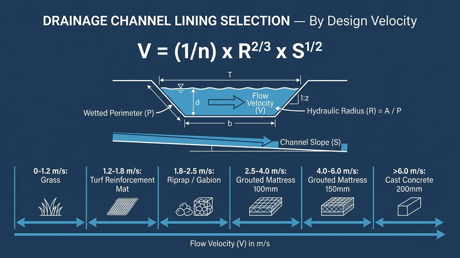
Drainage Channel Lining: Road and Infrastructure Guide
Drainage channels alongside roads, railways, and industrial sites carry high-velocity storm runoff that erodes unlined channels within seasons. This guide covers lining selection, hydraulic design, and installation for roadside drainage channels.
HydroBase - China Manufacturer
Ready to Specify Grouted Mattress?
GRI GT16 compliant products, factory test reports included. Engineering support at no cost. 48-hour response.