
How to Install Grouted Mattress: Contractor Guide
Quick Summary
A practical installation guide for grouted mattress (GGFM) contractors. Covers subgrade preparation, panel placement, grout mix design, injection sequence, curing, and common installation mistakes to avoid.
Quick Answer: Grouted mattress installation requires: prepared subgrade (trim to ±50 mm), fabric panels placed top-down on slopes and overlapped 300 mm, cement grout mixed at 1:2 cement:sand with w/c = 0.45–0.50, injected from the lowest point upward at 15–25 m³/hour, and cured for minimum 7 days with water misting. A single pump truck and crew of 6–8 installs 800–1,200 m²/day on flat or gently sloping surfaces. This guide covers every step with the practical details experienced contractors need.
Grouted mattress is not a complex system — but installation quality determines performance. The most common failures in the field trace to three mistakes: grout mix that is too wet (dilute grout, low compressive strength), injection from the wrong point (air trapped at the low end), and inadequate curing (surface drying before full hydration). This guide covers all the key steps and flags the common errors at each stage.
This guide is for contractors installing grouted mattress on canal lining, slope protection, river bank, and coastal revetment projects. For the hydraulic design basis, see Articulated Concrete Mattress: Technical Guide. For specific application guidance, see Canal Lining or Slope Protection.
Equipment Required
| Equipment | Specification | Notes |
|---|---|---|
| Concrete pump truck | 37–47 m boom, min 60 m³/hr capacity | Standard pump truck — no specialist plant required |
| Concrete mixer (batch) | 1 m³ minimum per batch | Or ready-mix truck supply if batching plant on-site |
| Injection nozzle set | HydroBase-supplied with rolls | Snap-fit to pump hose; do not improvise |
| Steel anchor stakes | 600 mm long, 16 mm dia. rebar | 2 m centres on slopes; 4 m centres on flat surfaces |
| Hessian covers / curing compound | 1 m overlap each side | Applied immediately after injection — do not wait |
| Water bowser | Minimum 5,000 L capacity | For curing mist — continuous water for 7 days |
| Excavator (subgrade prep) | 5–15 tonne, grading bucket | Standard plant |
Step 1: Subgrade Preparation
The most important step — inadequate subgrade preparation is the most common cause of poor installation quality. Requirements:
- Profile tolerance: trim the slope or canal invert to design profile within ±50 mm. Humps higher than 50 mm will cause the mattress to bridge the hump, leaving an unsupported void that can crack under load.
- Remove all vegetation: grass, roots, and organic matter decompose under the mattress and create voids. Strip to 100–150 mm depth below any vegetation.
- Compact: minimum 95% Standard Proctor Density for the top 150 mm. Loose fill will consolidate after grouting, causing the mattress to sag into voids.
- Moisture condition: the subgrade should be moist but not saturated or muddy. A saturated subgrade creates water channels that dilute the grout at the subgrade interface. Dry subgrade draws water from the fresh grout, accelerating setting and reducing workability — pre-wet dry subgrades the day before installation.
- Geotextile separator (where required): on subgrades with CBR <3% or gap-graded materials susceptible to piping, lay a 150 g/m² non-woven geotextile separator before the mattress.
Step 2: Panel Placement
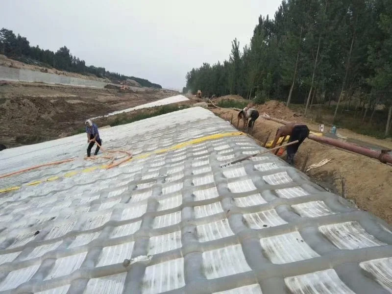
Panel placement sequence for slopes (work from crest downward):
- Position the roll at the top of the slope. The injection nozzles should be at the downslope end of the panel.
- Unroll the panel down the slope. Do not drag — roll the panel directly to avoid fabric damage.
- Drive anchor stakes through the top flap of the mattress at 2 m centres into the crest. Stakes should penetrate minimum 500 mm into competent material.
- Position the adjacent panel with 300 mm minimum overlap in the cross-slope direction. The upslope panel always goes on top (shingle lap — to direct water over, not under, the joint).
- If the canal or slope requires longitudinal panel joints (panels laid across the slope direction), overlap minimum 300 mm with the upflow panel on top.
- At the bottom of the slope, the terminal edge of the mattress should extend into a prepared toe trench (300 mm × 300 mm) or onto the flat canal invert for minimum 500 mm.
Common mistake: rolling the panel with the injection nozzles at the upslope end. This means grout must travel uphill from the nozzle — it will fill unevenly and air will be trapped at the upslope end. Always inject from the bottom of each panel upward.
Step 3: Grout Mix Design
The grout mix is simple but critical. The standard specification per GRI GT16:
| Component | Ratio | Notes |
|---|---|---|
| Portland cement (OPC) | 1 part by weight | CEM I or CEM II. For marine/sulphate: CEM III (GGBS) |
| Fine sand (clean, <5 mm) | 2 parts by weight | Silt content <5%. Washed river sand preferred. |
| Water | w/c = 0.45–0.50 | Do NOT exceed w/c 0.55 — strength drops below 17 MPa |
| Plasticiser (optional) | Per manufacturer dosage | Reduces w/c needed to achieve workability — recommended for hot weather |
Mix in a drum or paddle mixer — not a tilting drum truck mixer (inadequate shear for fine grout). Mix for minimum 90 seconds per batch. The fresh grout should have a flow cone time (ASTM C939) of 12–18 seconds — if it does not flow freely through the injection nozzle, add a plasticiser rather than water.
Most common mistake: adding water to improve workability. Adding water beyond w/c = 0.55 reduces 28-day compressive strength below 17 MPa (GRI GT16 minimum). Workability problems should be solved with a plasticiser, not additional water.
Step 4: Grout Injection
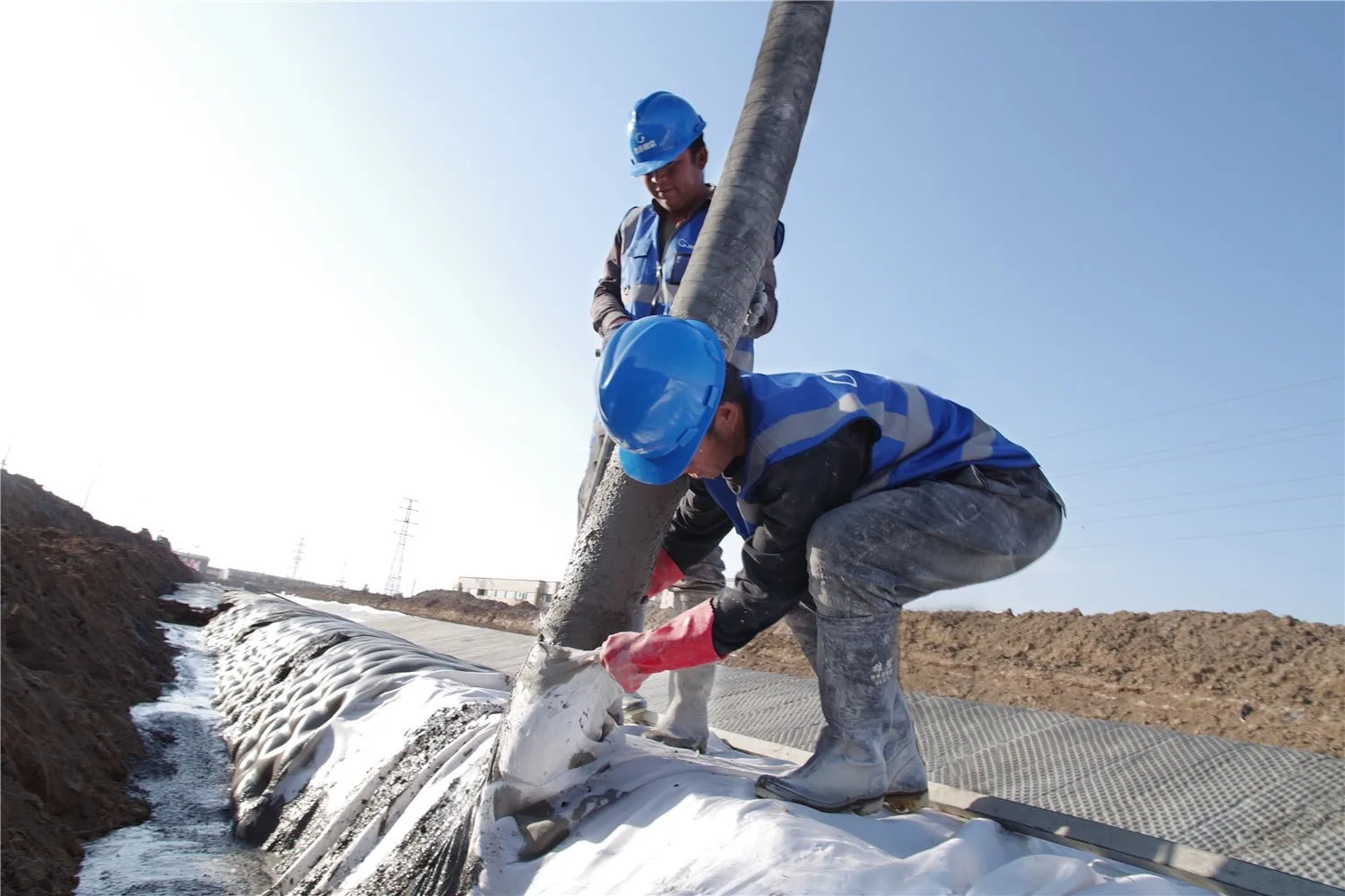
- Connect the pump hose to the injection nozzle at the base (downslope end) of the first panel.
- Begin pumping at 15–20 m³/hour. Increase to 25 m³/hour once the mattress is inflating uniformly.
- Watch for even inflation across the panel width. If one side inflates faster, reposition the nozzle toward the slow side.
- Move the nozzle upward along the panel as the bottom cells fill — typically in 2–3 m increments.
- The panel is full when grout begins to emerge from the top edge relief ports. Stop pumping immediately — overfill increases the risk of panel blowout at the seams.
- Connect to the next panel and repeat. Work across the slope in rows, completing each row before starting the next.
Common mistake: starting injection at the top of a slope panel. Grout flows to the bottom under gravity and the bottom cells fill before the top. When the injection point moves to the top, the bottom is already set — a cold joint forms at the mid-panel level. Always start at the bottom.
Step 5: Curing
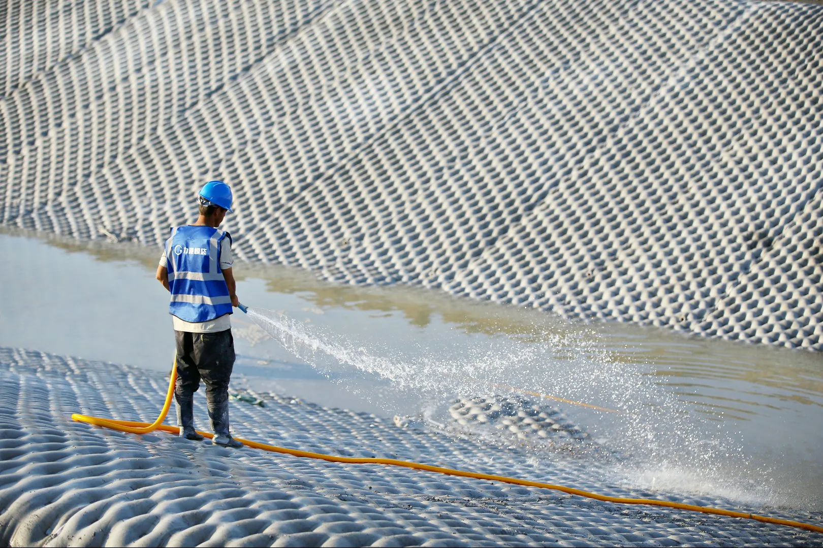
Curing is the step most frequently cut short on site — and inadequate curing is the most common cause of substandard 28-day compressive strength. Requirements:
- Apply hessian covers or curing compound immediately after completing each panel — do not wait until the end of the shift
- Mist with water every 2–4 hours during daylight hours for minimum 7 days
- In hot weather (>35°C) or high wind: increase misting frequency; protect with shade cloth if possible
- In cold weather (<5°C): use warm water in the grout mix; protect curing panels with insulating blankets; do not allow fresh grout to freeze
- Cube samples: take minimum 3 cube specimens per 500 m³ of grout placed; cure alongside the work; test at 28 days to confirm ≥17 MPa
Common Installation Mistakes and How to Avoid Them
| Mistake | Consequence | Prevention |
|---|---|---|
| w/c > 0.55 in grout | Strength < 17 MPa — GRI GT16 fail | Use plasticiser, not water, to improve flow |
| Injecting from top of slope | Air trapped at bottom; uneven fill | Always inject from the bottom edge upward |
| Insufficient panel overlap (<300 mm) | Joint opens under hydraulic load | Mark 300 mm lines on panel edges; check before stakes |
| No curing cover after pumping | Surface drying → strength loss → cracking | Hessian + mist immediately; designate curing supervisor |
| Subgrade with standing water | Grout diluted at interface; poor bond | Pump out standing water; allow surface to drain before laying |
Installation standards: GRI GT16 (Geosynthetic Research Institute) specifies acceptance criteria for grouted geotextile mattress systems including grout strength and fill uniformity. ASTM D4439 covers standard terminology for geosynthetics used in installation specifications.
Before installation, see our grouted mattress specification guide and our ACM technical guide for product selection.
Frequently Asked Questions
What pump pressure is required for grouted mattress installation?
Injection pressure at the pump is typically 4–8 bar for standard 100 mm mattress — well within the capacity of any standard boom pump. Pressure increases with mattress thickness (150–200 mm may require 6–10 bar) and with long horizontal pump runs. The injection nozzle restricts flow to maintain back-pressure in the panel — do not remove or modify the nozzle. If pressure exceeds 12 bar, stop and check for a blockage in the panel or injection line.
How many square metres can one crew install per day?
On flat or gently sloping surfaces with good access: 800–1,200 m² per pump unit per 8-hour shift. On steep slopes (1:1.5 to 1:2): 500–800 m²/shift. On underwater installations with diver assistance: 200–400 m²/shift. These figures assume a crew of 6–8 (pump operator, 2 panel handlers, 2 grout mixing crew, 1 curing crew, 1 supervisor). First-time crews typically achieve 60–70% of these rates until the injection sequence becomes routine.
Can installation continue in rain?
Light rain (<5 mm/hour) is acceptable — the pumped grout sets faster than rain can dilute it. Heavy rain (>15 mm/hour) should suspend operations: the grout mix can be diluted at the panel face before it sets, and curing covers become ineffective when saturated. Resume once rain stops and allow the freshly placed panels to be checked — panels placed during heavy rain should have cube samples tested and may need to be replaced if compressive strength results are borderline.
HydroBase provides installation manuals, grout mix design guidance, and on-site technical support for first-time installers. Contact our technical team before mobilisation — we will review your programme and flag any site-specific considerations. Download our installation specification as a starting point for your method statement.
HydroBase Technical Team
HydroBase manufactures grouted mattresses (GRI GT16 compliant) in China and delivers to 30+ countries. Our engineering team provides specification support, grout mix design, and installation guidance.
About HydroBaseMore Articles
View all
Grouted Mattress Case Studies: 5 Projects, Real Data
Five real grouted mattress installations across canal lining, river bank protection, coastal revetment, reservoir lining, and bridge pier scour — with actual project areas, design parameters, installation programmes, and post-installation performance data.
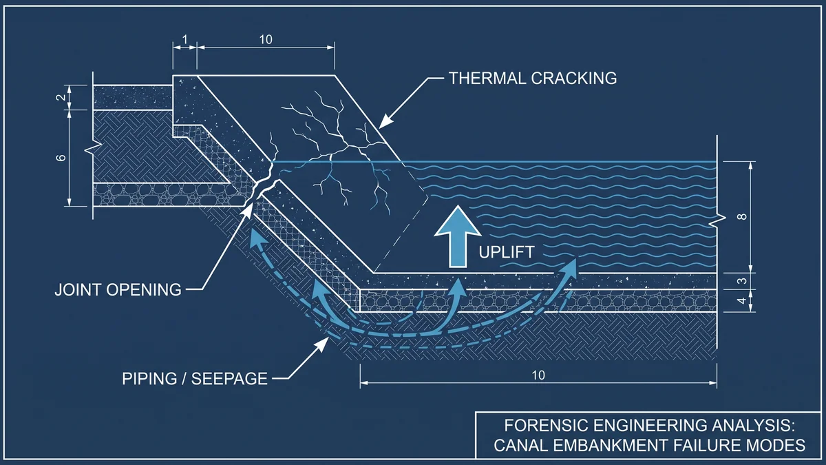
Canal Lining Failure: 7 Causes and How to Prevent Them
Canal lining failures cost irrigation authorities billions annually in emergency repairs and lost water. This forensic guide identifies the 7 most common failure causes — from joint failure to uplift — and explains how to prevent each through better specification and installation.
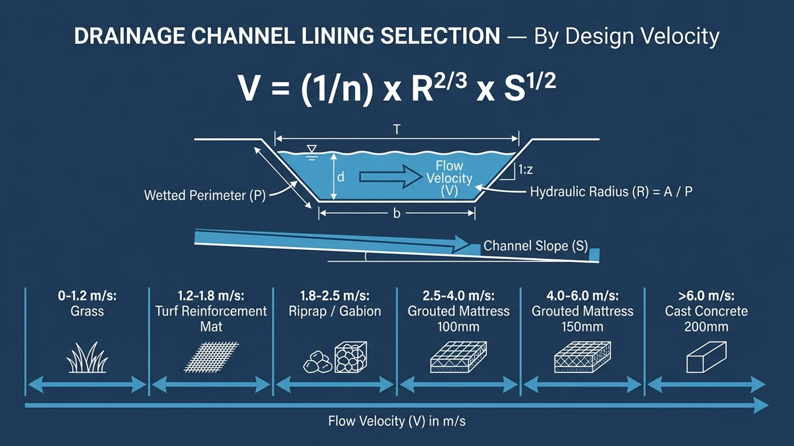
Drainage Channel Lining: Road and Infrastructure Guide
Drainage channels alongside roads, railways, and industrial sites carry high-velocity storm runoff that erodes unlined channels within seasons. This guide covers lining selection, hydraulic design, and installation for roadside drainage channels.
HydroBase - China Manufacturer
Ready to Specify Grouted Mattress?
GRI GT16 compliant products, factory test reports included. Engineering support at no cost. 48-hour response.