
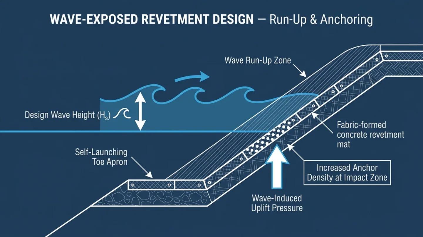
Fabric-Formed Concrete Revetment Mat: Design and Specification Guide
Quick Summary
Fabric-formed concrete revetment mat is designed differently for wave-exposed faces than for river current. This guide covers thickness selection by rated velocity, wave design differences and toe detail.
Fabric-formed concrete revetment mat design depends on whether the exposure is current-driven (river, tidal channel) or wave-driven (coast, reservoir with fetch). For current exposure, choose the thickness whose rated velocity exceeds the design velocity at the protected face. For wave exposure, velocity ratings do not cover the load: thickness and anchoring come from a wave analysis, with the toe designed for scour.
A revetment mat is a flexible armor layer on a bank or slope. Wave uplift is the upward pressure beneath a panel at the point of wave impact. A toe is an apron that settles into a developing scour hole instead of being undermined.
Revetment mat specification is sometimes carried over directly from canal lining practice, sizing thickness purely against a design velocity. That under-specifies wave-exposed sites, where the governing load is cyclic wave uplift and impact rather than steady current shear.
How Is Thickness Selected for Current Exposure?
For rivers and tidal channels without significant wave fetch, the design velocity at the protected face drives thickness. Compare it with the rated velocity of each thickness and choose the thinnest option that exceeds the design velocity with the margin your project design requires.
| Mattress thickness | Rated velocity |
|---|---|
| 75 mm | 2.5 m/s |
| 100 mm | 3.5 m/s |
| 150 mm | 4.5 m/s |
| 200 mm | 6.0 m/s |
Source: HydroBase design guidance. The standard hydraulic shear stress and Manning's n method applies to current-only sites. Local effects such as bends, transitions and turbulence near structures are for the designer to assess.
Wave-Exposed Design: What Changes
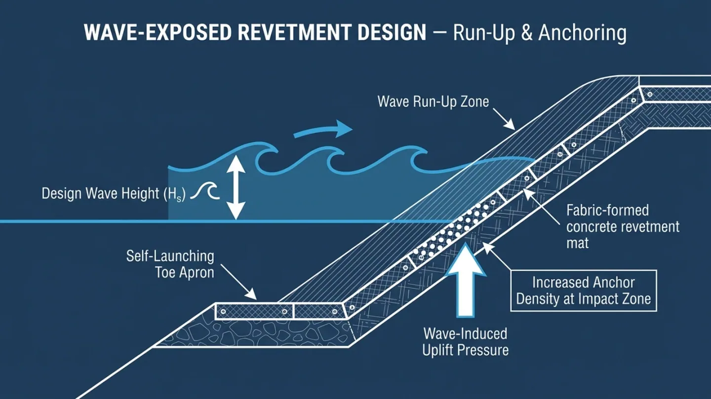
On a coastal seawall, a reservoir face with significant fetch, or any site exposed to wind-generated waves, the governing parameter shifts from steady hydraulic shear stress to:
- Wave-induced uplift pressure beneath the panel at the point of wave impact, which can exceed the panel's self-weight if anchoring is inadequate
- Cyclic loading at seams and anchor points from repeated wave action, rather than a single peak event
- Toe scour from wave reflection, particularly on steeper slopes where wave energy reflects rather than dissipates
Wave loads and run-up are normally assessed with methods such as those in the USACE Coastal Engineering Manual (EM 1110-2-1100) and CIRIA C683, The Rock Manual. The EurOtop manual is a different tool: it addresses wave overtopping discharge at crest level, not armor thickness or panel anchoring. For a flexible fabric-formed system, the designer then sets anchor density and thickness from the wave analysis, using more anchoring and, where fetch and wave height are significant, more thickness than a current-only design would give. The velocity ratings above do not describe wave capacity.
Current-Exposed Sites: The Standard Method
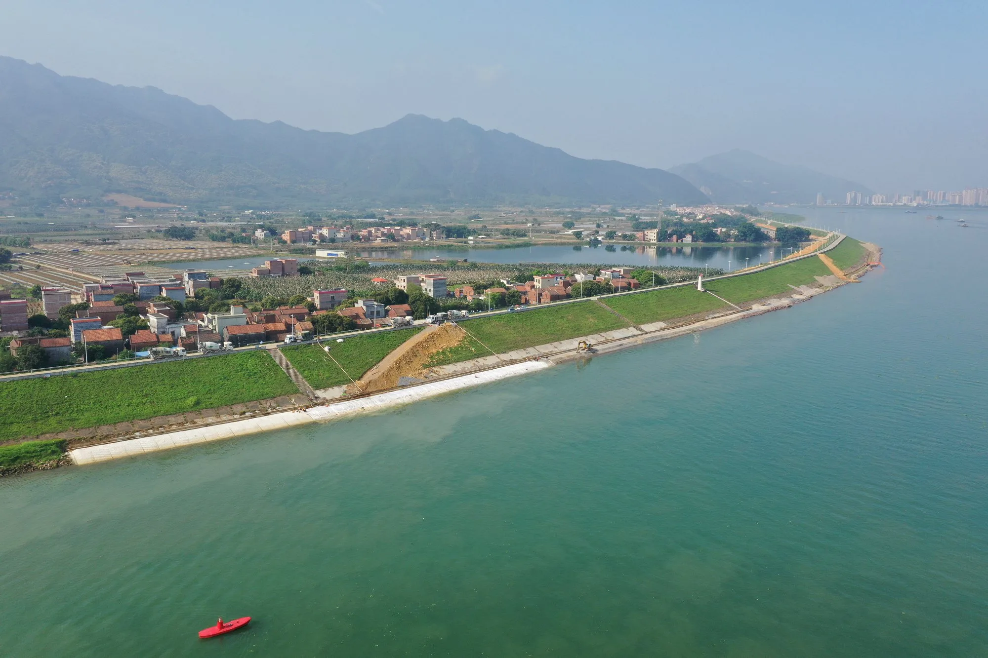
Where there is no significant wave fetch, the velocity-based method above applies directly. Check the toe, the upstream and downstream ends, and any transition to other lining types, because failure often starts at these edges rather than in the middle of the mat.
Anchoring and Toe Detail by Exposure
| Exposure Type | Anchoring Approach | Toe Detail |
|---|---|---|
| Current only (river, tidal channel) | Edge anchors at the panel perimeter | Toe key trench, with depth set by the scour assessment |
| Moderate wave exposure (sheltered coast, reservoir with limited fetch) | Higher anchor density at the wave impact zone, plus intermediate anchors | toe apron sized to the anticipated scour |
| Significant wave exposure (open coast, large-fetch reservoir) | Full-panel anchor grid, with thickness increased at the impact zone | toe apron, plus toe beam or sheet pile cutoff where scour risk is severe |
Specification Clause for Wave-Exposed Revetment
"Fabric-formed concrete revetment mat on wave-exposed faces shall be designed for the combined effect of hydraulic shear stress and wave-induced uplift pressure per the governing design wave height and period. Anchor density and panel thickness shall be increased above the current-only design baseline in proportion to the calculated wave load, and toe protection shall be to accommodate developing scour without loss of panel-to-toe continuity."
What Inputs Should the Designer Collect?
- Fetch length by direction, design wind speed and duration.
- Design wave height and period, and the water level range including surge or drawdown.
- Slope angle and subgrade profile, since steeper slopes reflect more wave energy.
- Scour estimate at the toe and the bed material.
- Whether pore pressure can build behind the panels, which decides standard or filter point fabric.
How Do You Confirm Performance After Installation?
Inspect wave-exposed panels after the first significant storm and then on a regular schedule. Early warning signs are lifting or tenting of panel edges at the impact zone, gaps opening between panel and subgrade, and loosening at anchor points. These appear well before structural failure, so a baseline survey of panel edges after installation gives the inspector something to compare against.
How Should Wave-Exposed Panels Be Built in Sequence?
- Construct the toe key trench or apron first, so the lower edge is secure before panels are filled.
- Deploy panels from the crest downward and anchor them at the crest before pumping.
- Work in weather and tide windows defined in the method statement.
- Install the denser anchors in the wave impact zone before filling, not after.
- Protect the surface from wave attack during curing where possible, following the curing requirements of the project specification.
What Questions Should a Design Review Ask?
- Is the governing load wave uplift, current shear, or both, and what is the evidence for the chosen wave height?
- Does the toe apron allow for wave-reflection scour as well as current scour?
- Is pore pressure behind the panels relieved, or is the fabric impermeable where it should not be?
- Is the anchor density at the impact zone higher than in the current-only baseline?
- What is the inspection trigger after the first significant storm?
What to Confirm Before You Specify a Revetment Mat
Before the clause is issued, check that it says which exposure governs. A document that mentions only velocity invites bidders to price a current-only design for a wave-exposed face, and the difference is hard to unpick after award. Confirm that the wave data has a named source and a stated return period, and that the author of the wave analysis is identified in the design basis.
Check that anchor density at the impact zone is written as a design output with an owner, not left to the installer. Look at the toe: the clause should say how scour is assessed and what happens at the free edge as scour develops. Confirm what the specification requires for grout testing, for placement windows and for the first post-storm inspection. A short review against these points before tender can expose gaps that would otherwise surface as variations on site.
Where This Design Approach Falls Short
This article separates current-driven and wave-driven exposure so a thickness is not chosen from a velocity alone. It does not provide a wave analysis, and it cannot give anchor density, anchor type or toe depth for any particular site. Those values come from the project designer working from site wave data, water levels, slope and ground. Open coasts with severe wave exposure, breaking waves on steep faces and sites with heavy overtopping may need armor that is not a flexible mat, and the coastal engineer decides that.
The geotechnical engineer must confirm the subgrade, the filter requirement and whether pore pressure can build behind the panels. The specification must set grout, testing and acceptance, and the method statement must set the tide and weather windows for placement. The sample clause in this article is a starting point for drafting, not wording to paste into a contract without review.
Sending Wave and Current Data to HydroBase
A revetment enquiry is easier to answer when it separates the two exposure cases. For current-only sites, send the design velocity at the protected face: thickness from 75 to 200 mm is rated 2.5 m/s, 3.5 m/s, 4.5 m/s and 6.0 m/s as thickness rises. For wave-exposed sites those ratings do not cover the load, so send the design wave height and period, the water level range, the slope drawings and the toe detail your designer intends. Say whether pore pressure can build behind the panels so the fabric type can be discussed.
Stock sizes dispatch in 3 to 5 days, and custom-size panels take 5 to 7 working days to produce at the factory in Inner Mongolia, China. Pricing is by project. Send the information through the contact page, and the engineering team replies within 48 hours.
Sources and Further Reading
Open each document to confirm its current edition and scope before you rely on it.
- EurOtop manual downloads: The wave overtopping manual for coastal and dike structures. Checked 2026-10-24 (link and title).
- PIANC publications: Catalogue of PIANC waterway and coastal engineering publications. Checked 2026-10-24 (link and title).
- Van der Meer Consulting, wave run-up paper (2013): Paper on wave run-up. Checked 2026-10-24 (link and title).
- FHWA HEC-23, Bridge Scour and Stream Instability Countermeasures: Guidance on selecting and designing scour countermeasures. Checked 2026-10-24 (link and title).
- GRI GT16: The manufacturing quality control specification for the geotextile fabric used in grout-filled mattress. Checked 2026-10-24 (link and title).
Frequently Asked Questions
How is design wave height determined for a reservoir or coastal revetment project?
For reservoirs, wave height is usually estimated from fetch length, wind speed and water depth using standard wave prediction methods. For open coasts, use measured or hindcast wave data and return-period statistics from the relevant national hydrographic or meteorological agency instead of fetch-based estimates alone. The designer should record the source and return period used.
Does filter point grouted mattress change the wave design approach?
Filter point variants help manage pore pressure behind the panel during wave-induced pressure cycling and rapid water level changes, which reduces the risk of uplift at the panel-to-subgrade interface. They do not replace anchoring: the filter openings relieve pressure, not mechanical restraint, so the anchor design still has to come from the wave analysis.
What inspection signs indicate a wave-exposed revetment is under-anchored?
Progressive lifting or tenting of panel edges at the wave impact zone, visible gaps between panel and subgrade, and loosening or wear at anchor points are the earliest signs. They typically appear well before any structural panel failure, so a baseline survey after installation and a post-storm inspection make the change easy to detect.
Send us your design velocity, fetch length or wave data and location. The HydroBase engineering team replies within 48 hours.
HydroBase Technical Team
HydroBase manufactures grouted mattresses (GRI GT16 compliant) in China and delivers to 30+ countries. Our engineering team provides specification support, grout mix design, and installation guidance.
About HydroBaseMore Articles
View all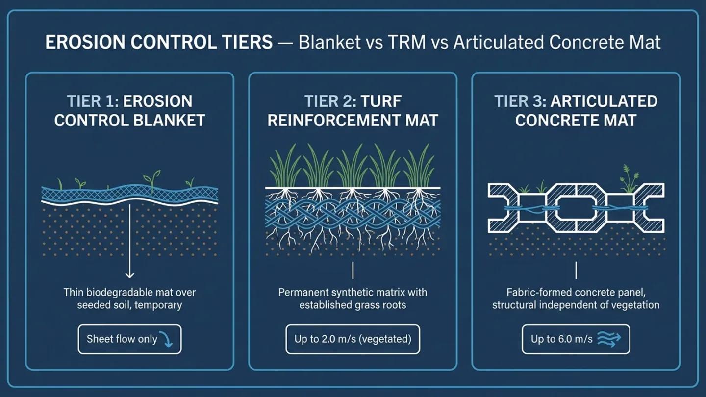
Erosion Control Blanket vs TRM vs Articulated Concrete Mat: Selection by Design Velocity
Three tiers of vegetated and structural erosion control: erosion control blanket, TRM, and articulated concrete mat. This guide sets out where each tier stops working and how to combine them.
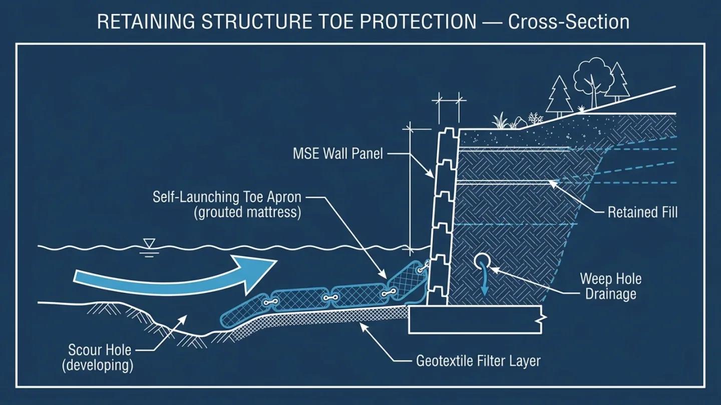
Erosion Control for Engineered Retaining Structures: MSE Walls, Canal Retaining, and Dam Toe Protection
Toe erosion and drainage problems are major risks for retaining structures, separate from the wall's structural design. This guide covers erosion control design at MSE walls, canal retaining structures and dam toes.
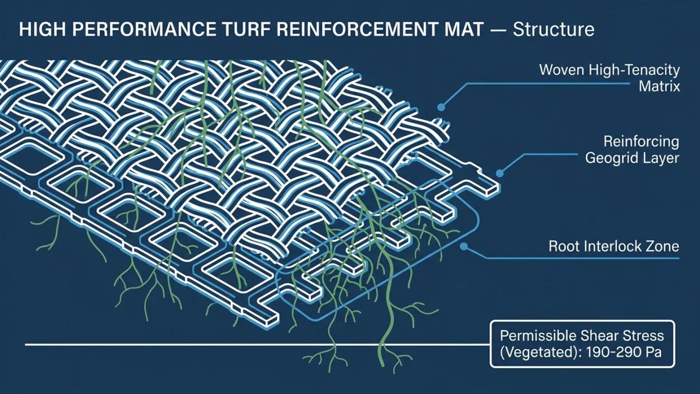
High Performance Turf Reinforcement Mat (HPTRM): Design and Specification Guide
High performance turf reinforcement mat extends vegetated erosion control into harder-working channels than standard TRM. This guide covers the shear stress design method, matrix types, specification wording and when to move to a structural system.
HydroBase - China Manufacturer
Ready to Specify Grouted Mattress?
GRI GT16 compliant products, factory test reports included. Engineering support at no cost. 48-hour response.